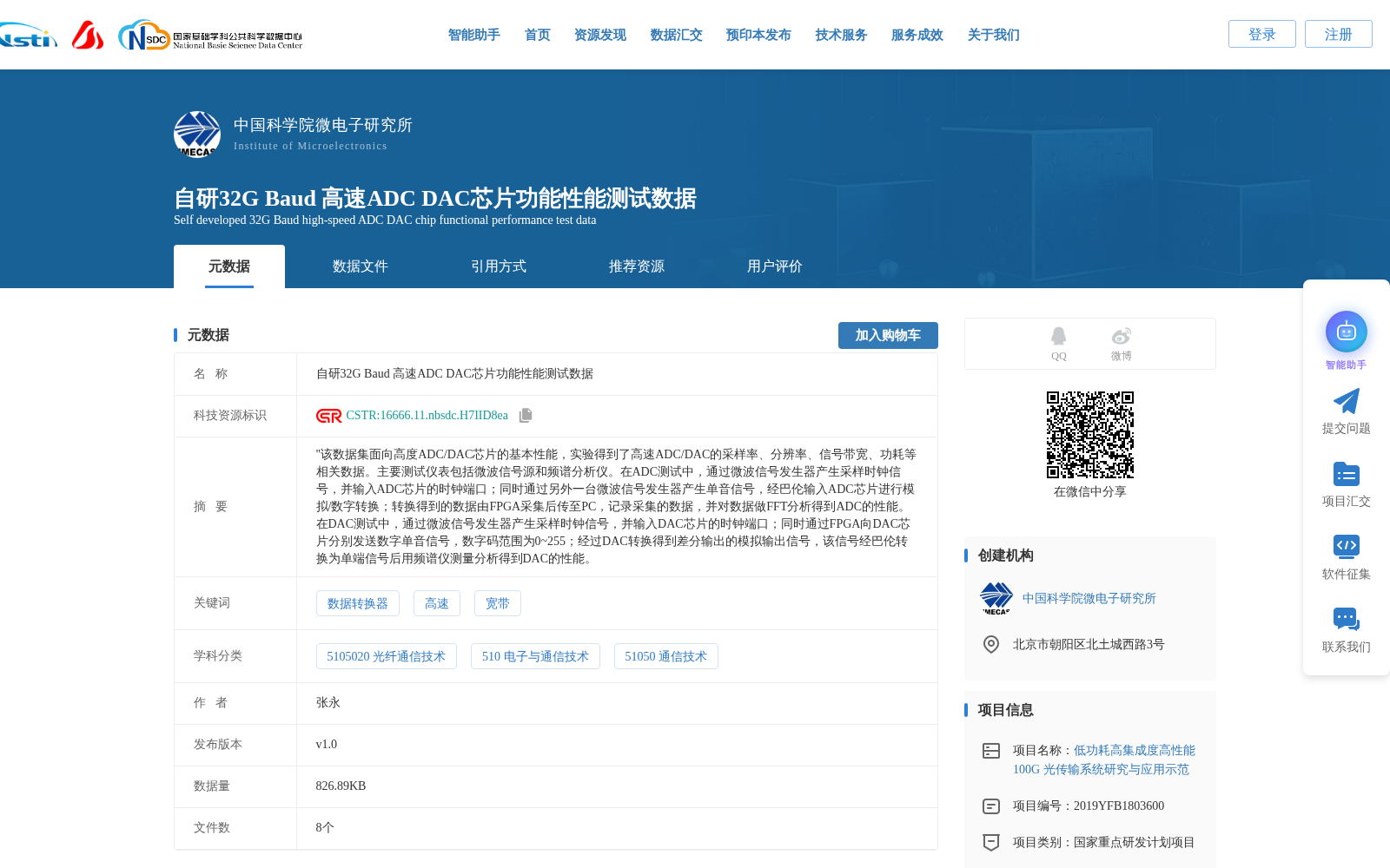
自研32G Baud 高速ADC DAC芯片功能性能测试数据
收藏资源简介:
"该数据集面向高度ADC/DAC芯片的基本性能,实验得到了高速ADC/DAC的采样率、分辨率、信号带宽、功耗等相关数据。主要测试仪表包括微波信号源和频谱分析仪。在ADC测试中,通过微波信号发生器产生采样时钟信号,并输入ADC芯片的时钟端口;同时通过另外一台微波信号发生器产生单音信号,经巴伦输入ADC芯片进行模拟/数字转换;转换得到的数据由FPGA采集后传至PC,记录采集的数据,并对数据做FFT分析得到ADC的性能。 在DAC测试中,通过微波信号发生器产生采样时钟信号,并输入DAC芯片的时钟端口;同时通过FPGA向DAC芯片分别发送数字单音信号,数字码范围为0~255;经过DAC转换得到差分输出的模拟输出信号,该信号经巴伦转换为单端信号后用频谱仪测量分析得到DAC的性能。
This dataset targets the basic performance of high-speed ADC/DAC chips, and collects relevant experimental data including sampling rate, resolution, signal bandwidth, and power consumption of high-speed ADC/DAC devices. The main test instruments include microwave signal generators and spectrum analyzers. For ADC testing: A microwave signal generator is used to generate a sampling clock signal, which is input to the clock port of the ADC chip; another microwave signal generator generates a single-tone signal, which is fed into the ADC chip via a balun for analog-to-digital conversion. The converted data is collected by an FPGA and transmitted to a PC, where the collected data is recorded, and FFT analysis is performed on the data to derive the performance metrics of the ADC. For DAC testing: A microwave signal generator is used to generate a sampling clock signal, which is input to the clock port of the DAC chip; meanwhile, the FPGA sends digital single-tone signals to the DAC chip individually, with the digital code range set as 0~255. The analog output signal with differential output is obtained after DAC conversion, which is converted into a single-ended signal via a balun, and then measured and analyzed by a spectrum analyzer to obtain the performance metrics of the DAC.